|
|
|

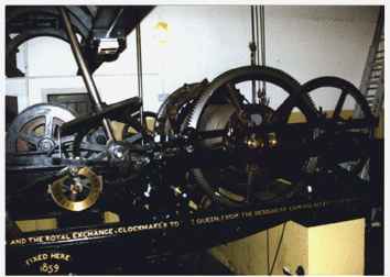
View of going and chiming trains Image courtesy of AEA Technology Starting from the left one can see the winding barrel of the going train, which is much smaller that those of the chiming and striking trains. In front of this is the brass 24 hour dial. The oblique shaft is the drive to the hands rising to the gantry above where it is distributed to the four dials. Just to the right of this may be seen the vertical arbor which drives the fly of the chiming train. It was the failure of this shaft which caused the 1976 disaster. Just to the right again is the large winding barrel of the chiming train and it is just possible to discern some of the cams at the rear of the barrel which operate the levers linked to the hammers of the bells. Slightly more to the right may be seen the cables rising to the quarter bells and directly below may be seen the cable from the winding barrel descending to the |